
With the rapid growth of the Internet data business scale and the explosive construction of supercomputers and data centers, the market size of high-speed interconnects products has been growing wildly, especially the large-scale commercial use of QSFP+ optical modules since 2012. As of the end of 2014, its market size has exceeded one billion US dollars per year. Due to the inherent individual differences of the VCSEL semiconductor lasers used in the QSFP+ SR4, modulation and performance testing of each QSFP+ has become a necessary measure to ensure product quality.
To reduce the fixed investment of test equipment and the expenditure on artificial workshops and make more effective use of existing resources, it is particularly important to analyze and improve the current test algorithm.
Improvement Ideas for Optical Power and Extinction Ratio of QSFP Transmitter
According to the characteristics of the VCSEL laser with a wavelength of 850 nanometers used in the QSFP+ SR4 optical module produced by our company, its threshold current is around 1mA, and the photoelectric conversion efficiency is about 0.45mW/mA. The chip driving the laser can output a maximum current of 12.7mA. This paper proposes a new debugging method to replace the old binary search method to improve the efficiency and consistency of modulation results.
Set the current DC of the laser driver chip to 2.7mA, 7.7mA, 12.7mA (the AC is set to 0 at this time) to obtain the corresponding optical power; then set the DC to 12.7mA, and then the AC component AC is 3mA, 6mA, 9mA, Obtain the corresponding extinction ratio. Draw the linear fitting of DC corresponding optical power and AC corresponding extinction ratio, respectively, as shown in Figure 1 and Figure 2.
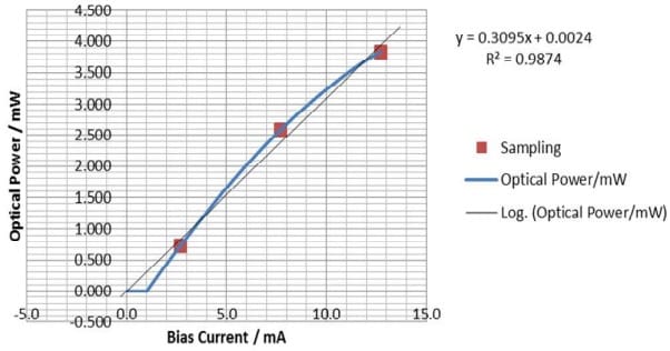
Fig.1 LASER tuning, current, and optical power linear fitting
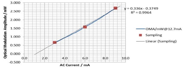
Fig.2 LASER tuning, current, and optical power linear fitting
Based on the two equations obtained by fitting, the DC and AC were directly modulated to the target values and then tested to verify.
Improvement Ideas for Sensitivity Test of QSFP Receiver
Before proposing improvement methods and ideas, we quantitatively analyze the existing testing methods.
Firstly, the most direct test method is adopted to gradually attenuate the optical signal power at the receiving end of the module to be measured. It takes 500 seconds for each attenuation to complete the bit error rate statistics to accurately obtain its sensitivity value. A total of 4 optical modules were tested, each with four receiving channels. The experimental results are as follows.
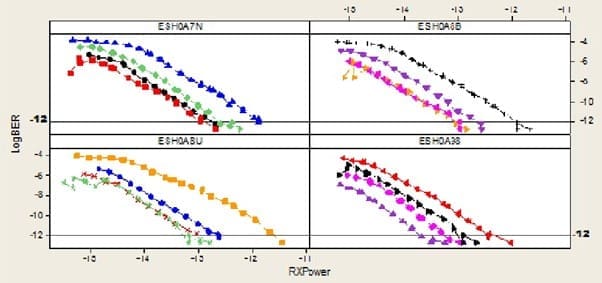
Fig.3 relationship between BER and Rx power
The horizontal axis in the figure represents the optical power reaching the receiving end in dBm; the vertical axis represents the bit error rate of the channel at this time, expressed as a logarithm with the base 10. The intersection of the test data connection and the horizontal line at BER 10E-12 is the receiver sensitivity value of this module’s channel.
As illustrated in the above figure:
1. The sensitivity difference between different modules is obvious.
2. Even the different channels of the same module (whose 4-way photosensitive chips were originally adjacent on the wafer) showed obvious differences.
3. When the bit error rate is large (>10E-6), and the bit error rate is small (<10E-12), the test data fluctuates greatly, and the test repeatability becomes worse.
4. For a long time, the method of using logarithmic fitting to estimate the light intensity of the bit error rate at 1E-12 is consistent with the actual test data.
86% of the time (400 seconds/464 seconds) of the sensitivity test of the optical receiving end using the dichotomy method is spent on finding the optical power corresponding to the bit error rate of 1E-11. An effective 1E-11 bit error rate mass production takes 50 seconds and generally requires eight dichotomies to find the corresponding optical power. How to reduce the number of steps in the dichotomy, especially in 1E-11, is one of the focuses of improving ideas. In addition, especially for the multi-channel condition of the QSFP+ module, it is obviously not advisable to measure four channels in sequence. However, when the dichotomy method is suitable for parallel testing, the test time is unstable, and multi-thread operation is required for parallel testing of different channels. Using multi-threading means that four non-interfering instrument control channels corresponding to 4 separate BER testers need to be prepared, and the final test time is determined by the channel that takes the longest. How to design a test method with fixed steps, time-consuming and stable to realize multi-channel parallel tests controlled by a single thread is the second key point of the improvement idea.
Conclusion
This paper briefly introduces the improvement ideas of the QSFPTEK 40G QSFP optical module transmitter and receiver test system. QSFPTEK has designed and implemented a complete automated test system based on the actual demand for QSFP+ optical module production testing in its own business, which is of great significance for improving module testing efficiency.
Featured Scottkipp, CC BY-SA 4.0 via Wikimedia Commons


